Hardware: the blade
The blade (or "plow") is a rigid printed part fixed to the toolhead. It pushes the parts, so the nozzle never touches them.
Why not push with the nozzle?
- The nozzle, heater block and heat break are the weakest parts of the toolhead. Side loads can loosen the nozzle or bend the heat break, and that shows up later as leaks.
- Nozzle probes (Voron Tap and similar) move the whole toolhead on a vertical rail. Side loads on that rail affect probing accuracy.
- Pushing with the nozzle needs it a fraction of a millimetre above the bed, so any Z error scratches the build surface.
Design rules
          side view                              front view
                                          ┌──────────── blade_width ────────────┐
       ┌─────────┐ toolhead               │                                     │
       │         ├──┐ mount plate         │            ┌───────────┐            │
       │         │  │ (existing screws)   │            │ toolhead  │            │
       │         │  │                     │            └─────┬─────┘            │
       └────┬────┘  │ arm                 │                  │ nozzle           │
            │       │                     ├──────────────────┴──────────────────┤
     nozzle ▼  ┌────┘                     │                blade                │
               │ blade ← blade_offset →   └─────────────────────────────────────┘
   ────────────┴──────── bed              lower edge = nozzle tip + blade lift
- Mount it on the carriage or a structural cover, not on the hotend or a fan duct. A nozzle probe's moving part is acceptable for light parts.
- The lower edge must sit above the nozzle tip (the blade lift, 1–2 mm), so the blade can never touch the bed before the nozzle would.
- The pushing face must be ahead of the nozzle in the push direction (
blade_offset), far enough that the parts never reach the hotend. - Wider than the toolhead. The blade must cover the toolhead's width, so parts outside the blade never hit the hotend or the duct from the side. 70–100 mm is typical.
- Make it stiff: PETG, ABS or ASA, 4+ walls, 40%+ infill, two arms, and a short lever.
- Chamfer the lower front edge so it rides over small bumps instead of digging in.
- Check the travel. At the drop edge the blade sticks out past the toolhead, so make sure it cannot hit the frame, the bed mounting hardware or cable chains anywhere along the edge.
Universal blade (recommended)
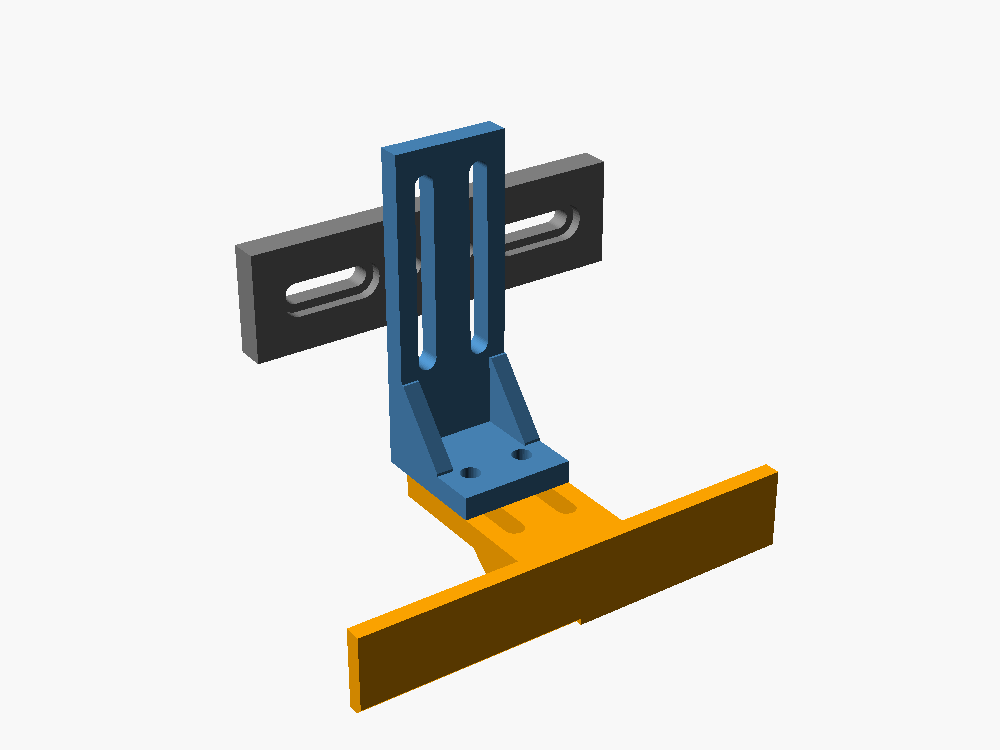
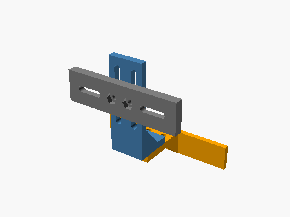
Three printed parts joined with M3 screws. Every joint is slotted, so one design fits most toolheads, nozzle heights and toolhead depths:
| Part | File | Adjusts |
|---|---|---|
| Blade | hardware/stl/blade_60mm.stl, blade_80mm.stl, blade_100mm.stl |
Reach: slots in the tab, ±10 mm |
| Arm | hardware/stl/arm.stl |
Height: slots in the upright, 30 mm of travel |
| Mount, screw version | hardware/stl/mount_screws.stl |
Fits toolhead screws spaced 28–50 mm apart |
| Mount, strap version | hardware/stl/mount_strap.stl |
For toolheads without usable screws: cable ties or a strap |
Height and reach only need to be roughly right. AUTO_EJECT_SETUP measures the exact values
after mounting (setup-wizard.md).
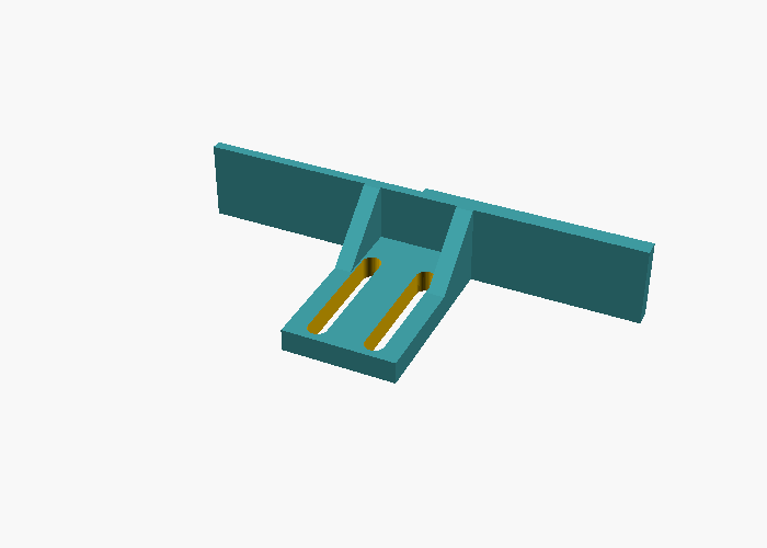
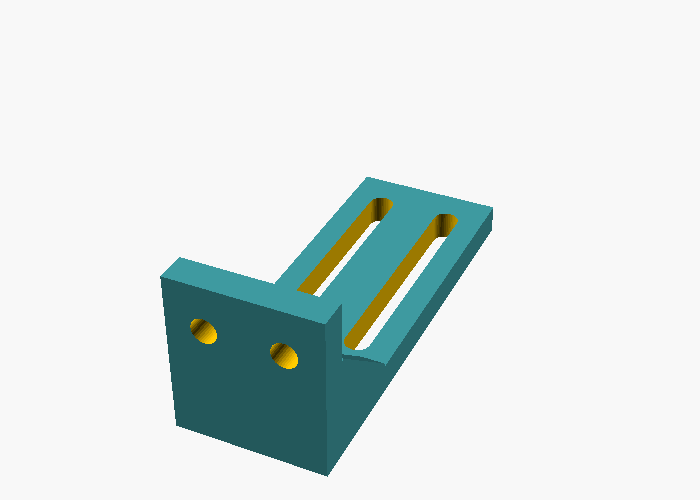
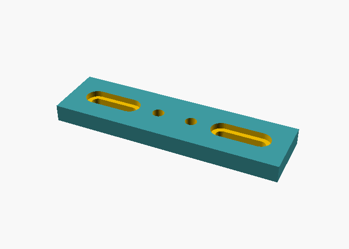
The STL files are already oriented for printing: no supports, and the arm lies flat so its layers run along the load.
Print settings: PETG, ABS or ASA (PLA softens near a hot bed). 4 walls, 40% infill, 0.2 mm layers.
Hardware
| Qty | Part | For |
|---|---|---|
| 2 | M3 × 10 screw + M3 nut | Arm foot to blade tab |
| 2 | M3 × 10 screw + M3 nut | Arm upright to mount (nuts sit in the traps on the mount's back) |
| 2 | Screws that fit your toolhead | Mount to toolhead (usually your existing front-cover screws, a few mm longer) |
Assembly
- Press two M3 nuts into the traps on the back of the mount.
- Screw the mount to the front of the toolhead.
- Bolt the arm to the mount through the upright's slots. Leave the screws loose.
- Bolt the blade's tab under the arm's foot. Leave the screws loose.
- Set the blade height with
hardware/test/blade_gauge.stl, a 1.5 mm strip: home the printer, move the nozzle over an empty part of the bed and down to Z 0.2, slide the gauge under the blade, loosen the arm screws and let the blade rest on the gauge. Tighten. The blade's lower edge now sits 1.5 mm above the nozzle tip, and its face must be ahead of everything else on the toolhead. - Run
AUTO_EJECT_SETUP.
Example: Voron Trident with Stealthburner
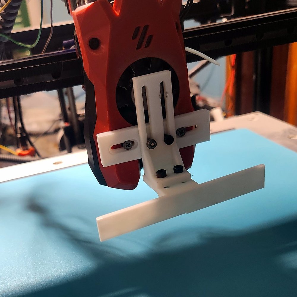
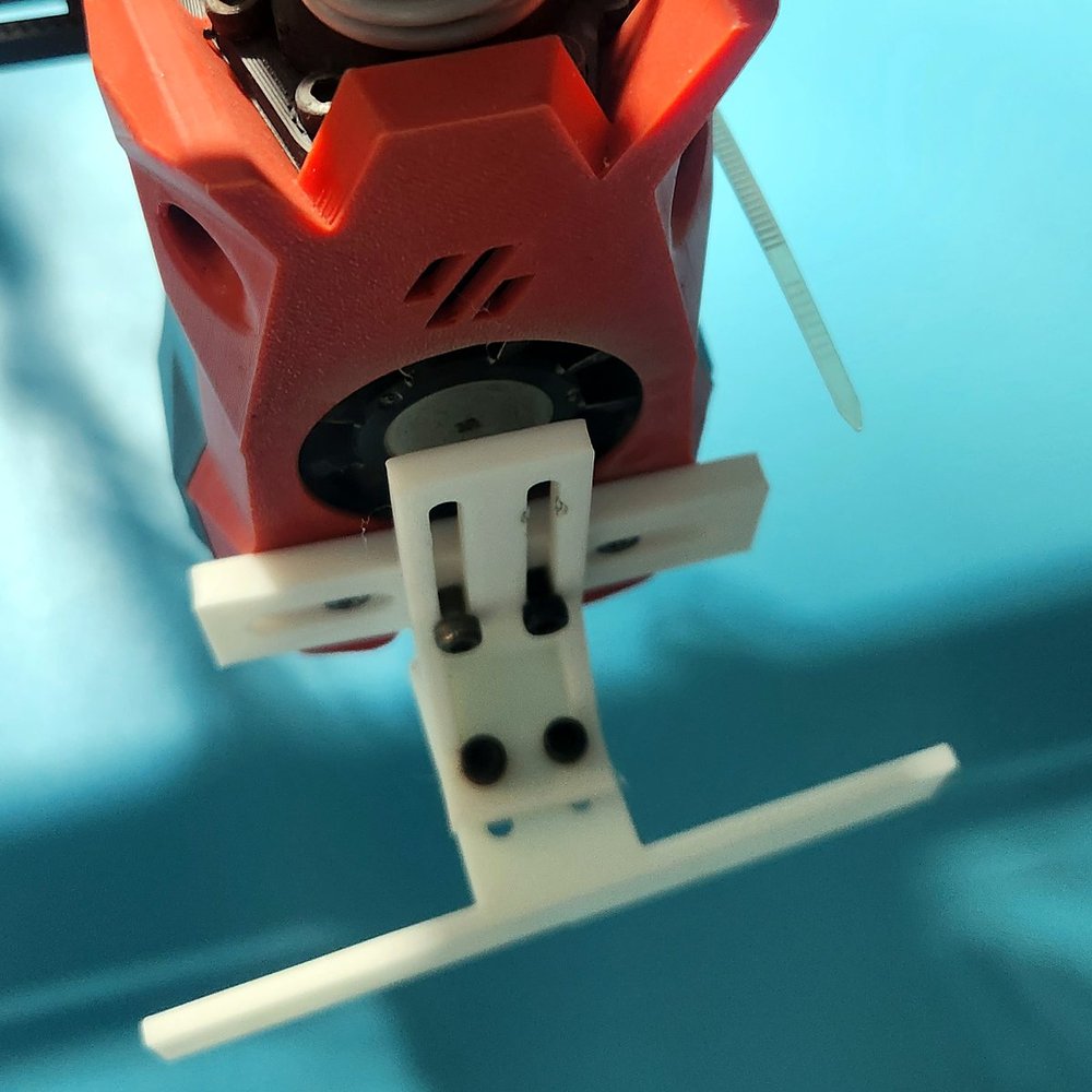
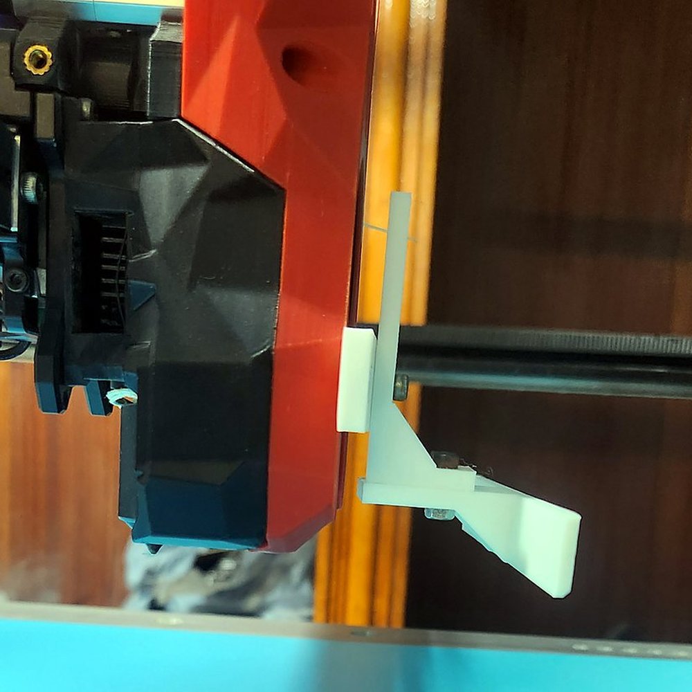
- The mount uses the two lower screws of the Stealthburner front cover, a few millimetres longer than stock.
- 100 mm blade. The arm upright sits in front of the hotend fan: keep it as low as the slots
allow, or print the arm with a smaller
arm_height, so it does not cover the fan intake. - Check the blade height (step 5 above) before homing. Voron Tap homes on whatever touches first, so a blade below the nozzle tip would set Z wrong.
Test parts
hardware/test/ has three parts for the setup and a first run:
test_hollow_cube.stl: a 25 × 25 × 10 mm square ring with 1.6 mm walls, like a cookie cutter. Print two or three and eject them while you watch.calibration_block.stl: a low 20 × 20 × 3.5 mm block forAUTO_EJECT_CALIBRATEand the setup. Print it solid (100 % infill) anywhere but the middle of the bed and leave it stuck: the setup finds it and homes around it. It is low so the fan duct under the toolhead cannot reach it. Measure right after the print, while the bed is still warm (55 °C at most) and the block well stuck: on sheets that release cold parts, a cooled block can slide.blade_gauge.stl: a 1.5 mm strip to set the blade height (assembly step 5).
All three come from test_parts.scad if you want other sizes.
Make your own size
hardware/universal_plow.scad has every dimension as a parameter: blade width and height, arm
length, slot lengths, mount screw range and screw size. Open it in OpenSCAD, use the
Customizer panel, choose the part, then Render (F6) and Export as STL. From a terminal:
Toolhead adapters
If your toolhead needs a dedicated mount, add it to
hardware/adapters/ and open a pull request, so others with the same
toolhead can use it.
Single-piece template
hardware/plow.scad is a simpler one-piece blade with a fixed two-screw
mount, for when you design around one specific toolhead.
Measuring
With Voron Tap or another probe that touches with the nozzle, let the printer do it: print the
calibration block, leave it on the bed and run AUTO_EJECT_CALIBRATE
(setup-wizard.md). Otherwise, measure by hand with the
hotend cold and the printer homed.
blade_offset: move the nozzle to the centre of the bed and lower it to Z=5. Measure along the push axis from the nozzle tip to the blade's pushing face. Positive means the face is ahead of the nozzle in the push direction.blade_width: measure across the push axis. If the blade is not centred on the nozzle, use twice the distance from the nozzle to the shorter side.- Blade lift: with the nozzle touching a sheet of paper on the bed (Z≈0), the gap under the blade should be the lift you designed (1–2 mm).
push_z: the blade's lower edge ends up atpush_z + lift. Start atpush_z: 3.0, watch a real eject, then lower it until the blade reliably catches your parts at 1.5–3 mm above the bed.push_end: with"auto", the push runs to the axis limit. Check that at the limit the blade's face is past the edge of the build surface. If it is not, the parts land on the bed's edge instead of falling. Lengthenblade_offsetin the hardware if needed.
Catching the parts
A cardboard box, a bin or a printed chute under the drop edge. Leave room for the bed to move in Z if your bed moves vertically, and keep cables away from the drop zone.
Bed surfaces
| Surface | Releases when cool? |
|---|---|
| Textured PEI | Yes, PLA/PETG release below ~30 °C |
| Smooth PEI | Yes, but PETG can bond too strongly. Use a release agent |
| BIQU CryoGrip | Yes, PLA slides off once cooled |
| Glass | Often, but brittle. Not recommended |
| Garolite / G10 | Nylon releases well |
Always check by hand first: once the bed is cool, a part should slide off with a finger push. If it needs flexing the sheet, auto-eject will not work on that surface.